1. Cargo Weight
① Cargo weight refers to the total weight of the cargo including all dunnage, shoring, and lashing materials.
The total cargo weight must not exceed the container’s maximum payload.
② The values shown in the table below may vary slightly depending on the container’s year of manufacture and production series.
Where cargo weight is high and accurate confirmation is required, the carrier should be consulted in advance to assign an appropriate container.
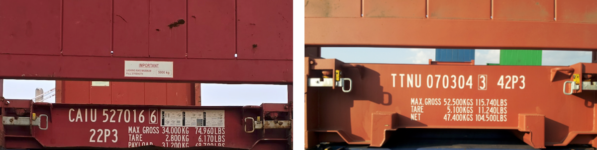
| Max. Payload | 20′ | 40′ |
|---|---|---|
| Flat rack | 27~31 Ton | 39~47 Ton |
| Open top | 28 Ton | 26~28 Ton |
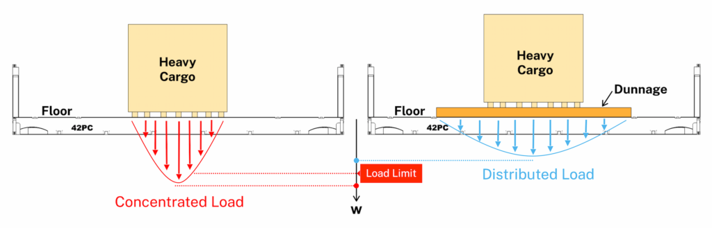
③ Where cargo is heavy but has a small footprint, resulting in concentrated loads on a limited floor area, the container floor load limits must be considered and the load distributed over a wider area to prevent damage to the cargo and container.
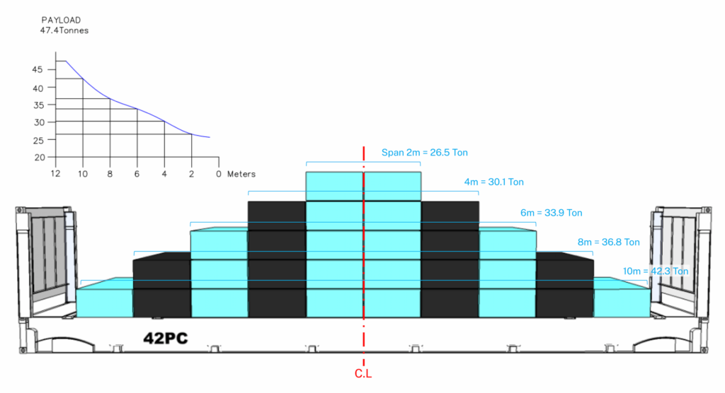
④ Below is an example of a loading chart for a 40’ flat rack with a maximum payload of 47.4 tons.
The chart shows the allowable load limits by cargo length, assuming the cargo weight is evenly distributed over the entire floor in the fore-and-aft direction, centered on the flat rack’s center line.
2. Load Distribution
Flat rack containers are special containers designed to transport heavy cargo with concentrated loads, unlike standard containers.
However, where cargo length or width is short and floor load limits are exceeded, installing dunnage can distribute the load over a wider area, thereby reducing the maximum load applied to the container floor structure.
2.1 Load Distribution (Longitudinal)
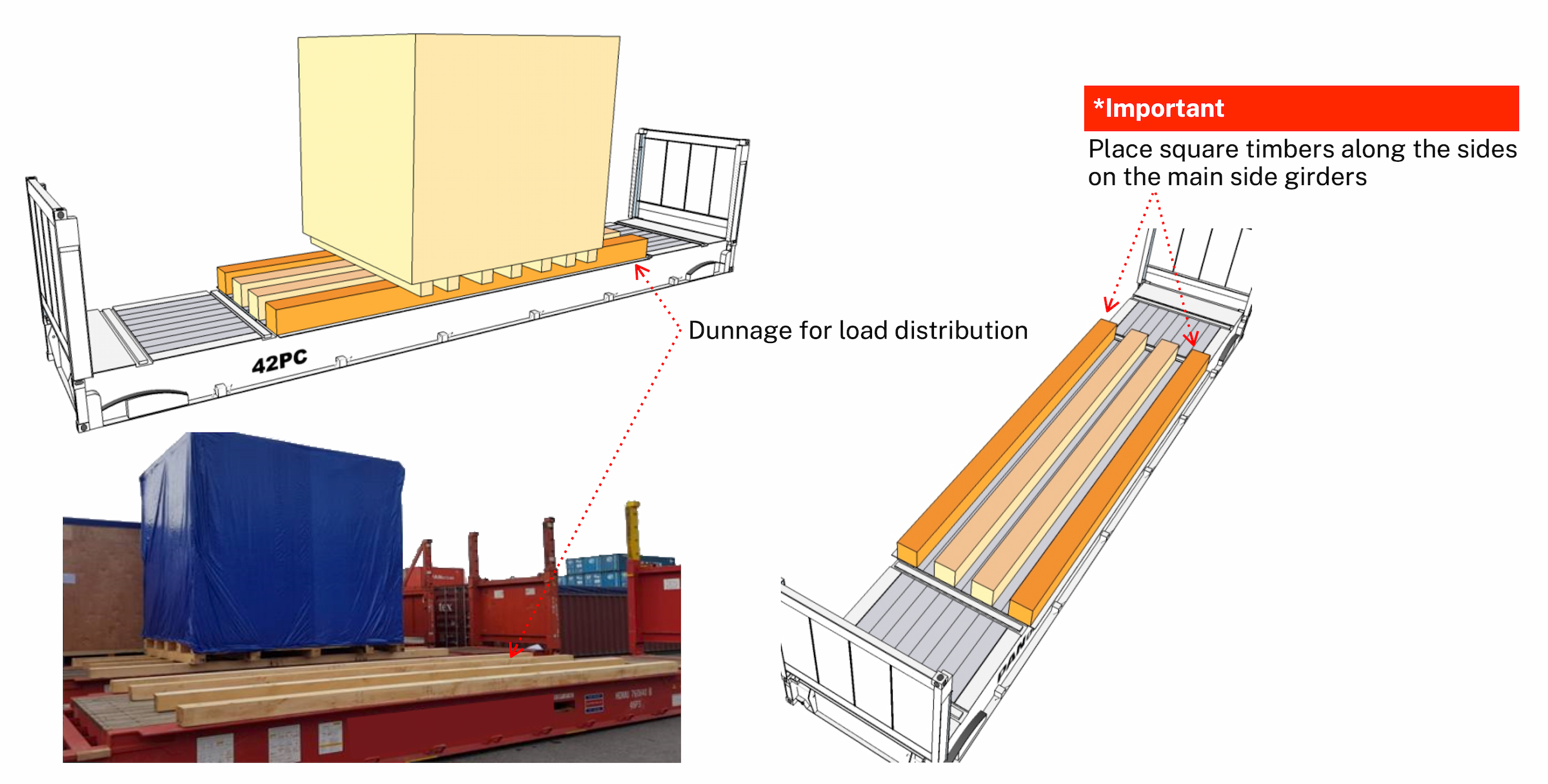
① When cargo length is short and weight is concentrated over a limited longitudinal area, dunnage must be installed to distribute the load forward and aft.
② The primary load-bearing structure of a flat rack consists of H-beam-type bottom side rails on both sides.
Between these rails, ladder-type cross members are installed, which support the cargo weight and transfer loads to the bottom side rails.
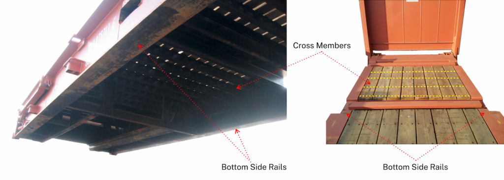
③ Due to these structural characteristics, dunnage must be placed directly on the bottom side rails, and cargo must not rest solely on the wooden floor panels.
④ Minimum width of square timber for load distribution
- 20′ Flat rack: Minimum 10 cm
- 40′ Flat rack: Minimum 15 cm
2.2 Load Distribution (Transverse)
① When cargo length is sufficient but width is narrow, transverse dunnage may be installed to distribute the load laterally.
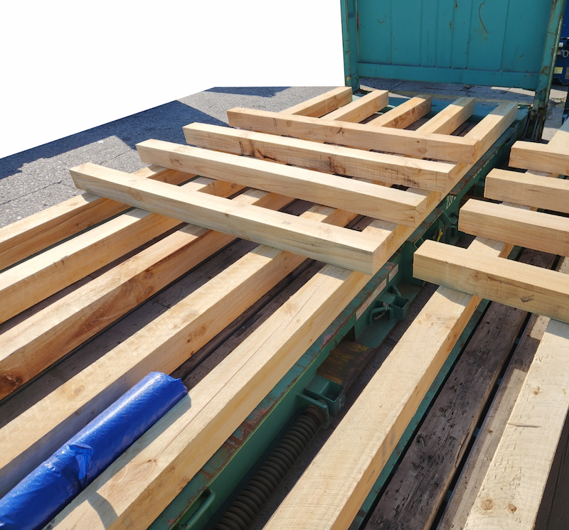
② Dunnage must be long enough to rest on the side girders of both bottom side rails.
Cargo weight must not be concentrated solely on the wooden floor.
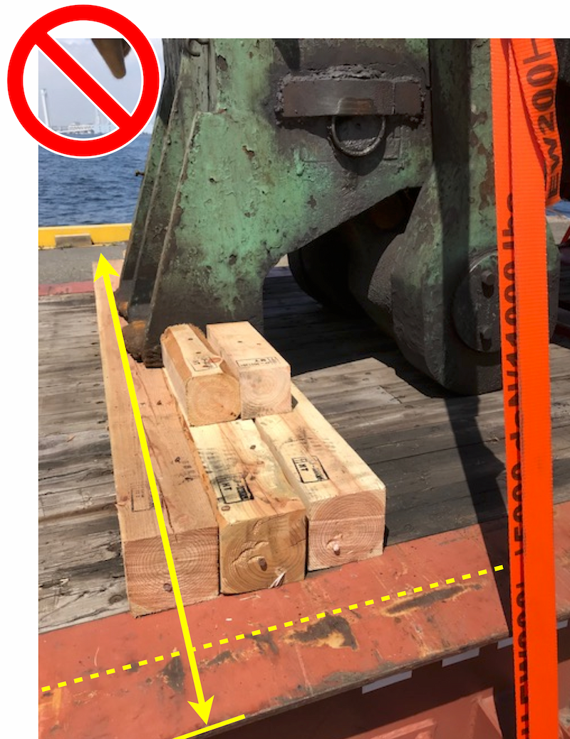
- Short dunnage causes cargo load to concentrate on the central floor area, creating a risk of cross member deformation or collapse.
- Dunnage must extend to the main side girders (indicated by yellow lines) to allow the bottom side rails to carry the load.
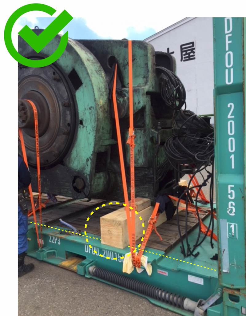
- Dunnage fully spans both bottom side rails, allowing the primary structural members to directly support the cargo weight.
③ Minimum width of square timber for load distribution
- 20′ Flat rack: Minimum 10 cm
- 40′ Flat rack: Minimum 15 cm
2.3 Load Distribution (Longitudinal + Transverse)
① When both cargo length and width are short, combined longitudinal and transverse dunnage should be installed to distribute the load in both directions.
② Minimum width of square timber
- 20′ Flat rack: Minimum 10 cm
- 40′ Flat rack: Minimum 15 cm
3. Load Position
① The basic principle of cargo positioning is that the cargo shall be arranged and secured so that its joint centre of gravity is located close to the mid-length and mid-width of the container, thereby avoiding eccentricity of the centre of gravity in both the longitudinal and transverse directions.
② The center of gravity (COG) should be positioned as close as possible to the container center line, and generally must not exceed ±5%, in accordance with crane operational limits.
③ For offset cargo, when using a spreader with adjustment capability, offsets of up to ±10% may be permitted depending on equipment specifications.
(Source: CTU Code Annex7. Packing and securing cargo into CTUs 3.1.4 Principles of packing)
Determination of Longitudinal Center of Gravity
Where eccentricity of the center of gravity is anticipated, the precise longitudinal position of the joint center of gravity may be determined by calculation in order to assess stuffing feasibility and cargo positioning in advance.
Example Cargo Information
- No.1 Box: L 5,000 x W 2,600 x H 2,200 mm, 2 Ton
- No.2 Box: L 6,500 x W 2,500 x H 2,500 mm, 23 Ton
Even when Box No.1 is positioned as close as practicable to the end wall in an attempt to minimize eccentricity, calculation results indicate that the joint center of gravity is offset by approximately 32% from the mid-length of a 40’ flat rack container.
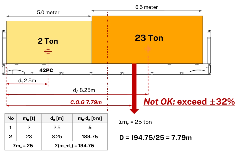
In this case, due to excessive eccentricity combined with high cargo weight, the two boxes cannot be loaded onto the same 40’ flat rack container.
Accordingly, the cargo must be allocated as follows:
- No.1 Box → 20’Flat Rack
- No.2 Box → 40’Flat Rack
④ Where the cargo weight approaches the crane’s SWL (Safe Working Load), even minor eccentricity may result in the exceedance of equipment load limits.
In such cases, the joint center of gravity should be positioned as close to zero eccentricity as practicable.
| Cargo Weight Condition | Acceptable Eccentricity of COG (Practical Guideline) |
|---|---|
| Well below Crane’s SWL | ±5~10% |
| Close to Crane’s SWL | As close to 0% as practicable |
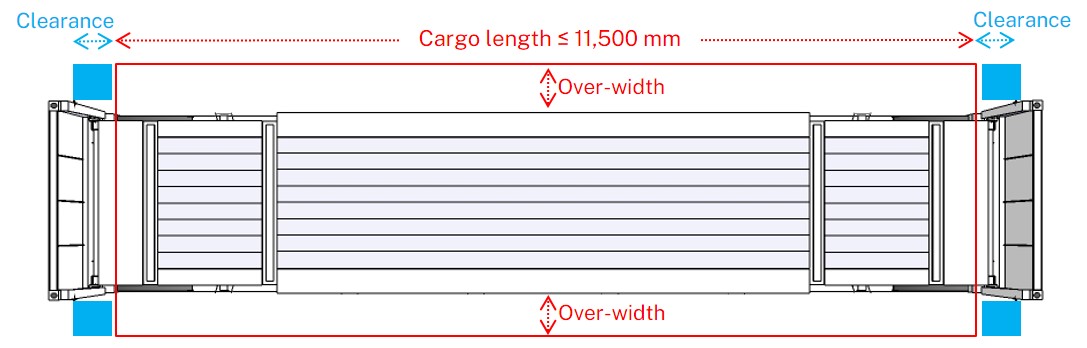
4. Under-Deck Stowage Criteria for OOG Cargo
① Where OOG cargo stuffed on a flat rack has over-width, sufficient clearance must be maintained from the corner posts to prevent contact with cell guides and entry guides inside the vessel’s under-deck cargo hold.
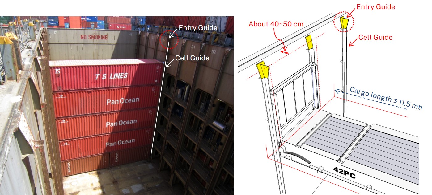
② For OOG cargo with over-width, cargo length must not exceed 11.5 m to avoid interference with the entry guide and cell guide (blue-highlighted areas), in order to be eligible for under-deck stowage.
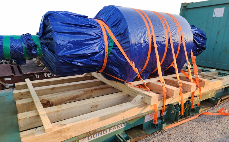
5. Lashing Material
① Different types of lashing materials (e.g., belts and wires) must not be mixed for the same cargo.
In particular, the same type of lashing material must be used in the same direction, as different materials have different elasticity characteristics.
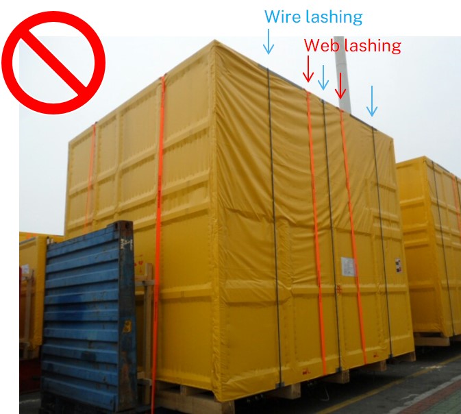
- Wire ropes and web lashings have different elastic properties, causing uneven load sharing under dynamic forces during transport.
- This may result in excessive loads on specific lashings or the cargo, leading to damage or failure.
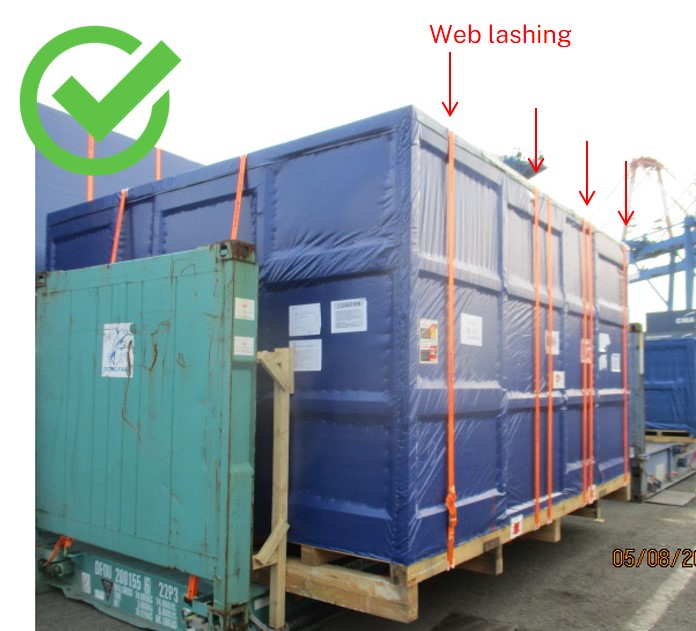
- Using only one type of lashing material ensures uniform lashing strength, allowing forces to be evenly distributed and improving transport safety.
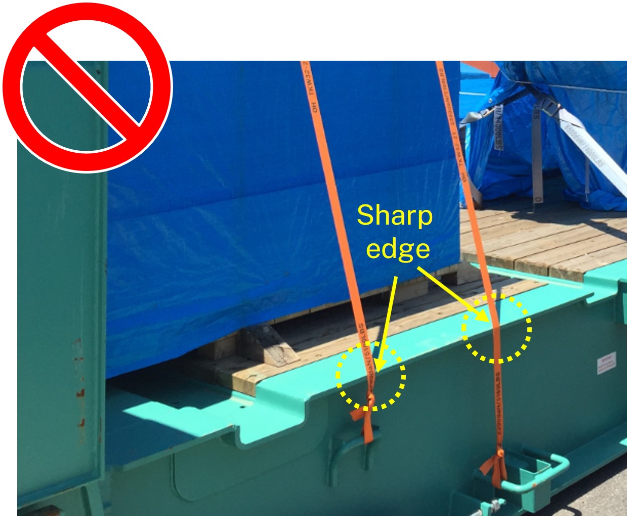
② Installation of Edge Protectors
Where web belts or wire ropes contact sharp cargo or container edges, or where lashing tension may deform cargo edges, edge protectors must be installed.
Edge protectors prevent abrasion or cutting of lashing materials and distribute lashing pressure over a wider area to protect cargo surfaces.

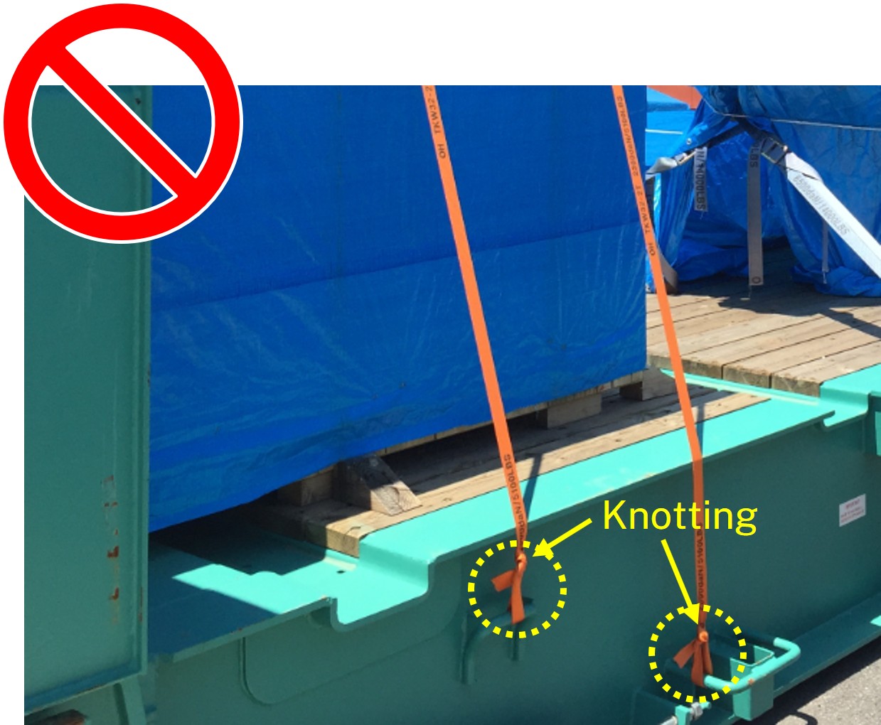
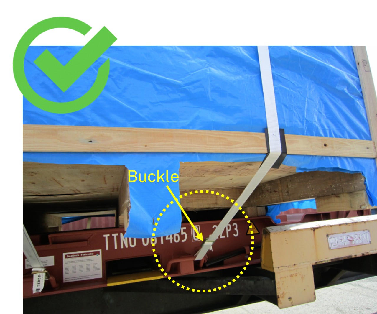
③ Knots must not be used on lashing belts, as tying knots can reduce tensile strength by up to 50% or more.
Lashing belts must be secured using approved buckles or ratchet devices, which ensure stable lashing tension throughout transportation.