

The fact that a Dry Container has a maximum payload of 28 tonnes does not mean that a single 20-tonne Coil can be loaded into it.

The maximum payload is the limit for the combined weight of the cargo and all securing materials loaded into the container. Cargo such as a Coil, however, has a small contact area and concentrates substantial weight. The Floor Line Load, local loading, strength of the Bottom Crossmembers, Bedding arrangement, and securing capacity must therefore be assessed separately.
Dry Containers used in actual maritime transport also vary in manufacturing year, manufacturer, floor construction, repair history, and present condition. A carrier’s conservative Load Limit should therefore be understood not merely as a restriction, but as an operational criterion for managing the structural uncertainty inherent in a mixed fleet of containers in different conditions.
1. Limits to Be Checked for a Dry Container
When assessing whether a heavy Coil can be loaded, at least the following four limits must be distinguished:
| Assessment item | What must be checked |
|---|---|
| Max. Payload | Total loaded weight, including the Coil, Cradle, Bedding, Blocking, and Lashing materials |
| Floor Line Load | Weight acting on the container floor per metre of container length |
| Local Floor Strength | Local load concentrated on the floor panels and individual Bottom Crossmembers |
| Securing Capacity | Ability of the Blocking, Bracing, Lashing, and Anchor Points to withstand the inertial forces generated during transport |
Even when the maximum payload is not exceeded, insufficient Bedding length can concentrate the load on only a few Bottom Crossmembers. Conversely, even if the vertical load is adequately distributed, insufficient Blocking and Lashing can allow the Coil to move or overturn.
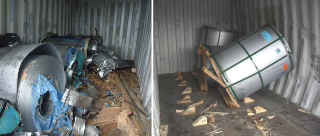
Loading a heavy Coil into a Dry Container must therefore be assessed as one integrated system:
Distribution of the vertical load through Bedding → Support of the Coil by a Cradle → Prevention of movement through Blocking and Bracing → Prevention of overturning and residual movement through Lashing
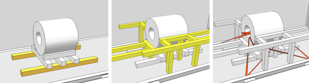
2. Load-Transfer Path of a Coil
The floor of a Dry Container generally consists of timber or bamboo plywood flooring supported by transverse Bottom Crossmembers beneath it.
The weight of a Coil is transferred through the following path:
Coil → Cradle or Saddle → Longitudinal Bedding Beams → Floor panels and multiple Bottom Crossmembers → Left and right Bottom Side Rails → End Frames and Corner Fittings
If a Coil is placed directly on the floor or on short supports, the load will be concentrated on only a few Crossmembers. This can cause not only indentation or failure of the floor panels, but also permanent deformation of the Crossmembers and damage to their connections with the Bottom Side Rails.
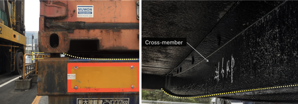
By contrast, sufficiently long Bedding Beams installed in the longitudinal direction of the container transfer the load to a greater number of Crossmembers. Bedding is not merely timber placed beneath the cargo; it is a structural arrangement that defines the load-transfer path of heavy cargo.
3. Load Limits for Dry Containers
How were the 4.5 ton/m criterion for a 20′ container and the 3.0 ton/m criterion for a 40′ container derived?
The following figures used by some carriers are better understood as conservative operational criteria based on the representative payloads of earlier containers and notional calculation lengths, rather than as absolute limits directly prescribed by ISO for every container.
20′ Dry Container
Representative specifications for earlier 20′ containers were as follows:
- Maximum Gross Mass: approximately 20.32 tonnes
- Tare: approximately 2.3 tonnes
- Payload: approximately 18 tonnes
- Reference length for the line-load calculation: approximately 4 m
Excluding 1 m at each end does not mean that the ends of the container are structurally weak or cannot be used for cargo. It is a notional reference length established by deducting 1 m at each end from the container’s overall length of approximately 6 m.
40′ Dry Container
- Representative payload: approximately 26.7–27 tonnes
- Reference length for the line-load calculation: approximately 9 m
The 9 m value is likewise a notional reference length established by deducting 1.5 m at each end from the container’s overall length of approximately 12 m.
This calculation method is described in the Container Handbook. Many modern containers have higher payload ratings than earlier equipment. These figures should therefore be understood as conservative common criteria for equipment of different ages and specifications, rather than as precise calculations of the actual structural capacity of every modern container.
Neither 4.5 ton/m nor 3.0 ton/m is an absolute standard uniformly applicable to all ISO containers, and carrier requirements are not identical. The applicable carrier’s latest requirements and the specifications of the individual container must therefore take precedence.
4. Why Conservative Load Limits Are Necessary
Modern Dry Containers often have higher payload ratings and structural performance than older equipment. Nevertheless, carriers have practical reasons for continuing to apply the longstanding criteria of 4.5 ton/m and 3.0 ton/m.
The fleets operated by carriers include a mixture of:
- Containers from different manufacturers and manufacturing years
- Carrier-owned and leased equipment
- Containers with timber, bamboo plywood, or steel floors
- Equipment whose floor panels and Crossmembers have been repaired several times
- Equipment with corrosion, permanent deformation, or bent Bottom Crossmembers
- Equipment whose repair quality and residual strength are difficult to determine accurately in the field
A container that has been properly inspected and correctly repaired should remain cargo-worthy. It would therefore be inaccurate to assume that every repaired container is structurally weak.
However, the Approved Continuous Examination Programme (ACEP) under the CSC is intended to ensure that containers are examined regularly and maintained in a safe condition. It does not individually approve the local loading or Bedding design for a specific Coil.
For a carrier, maintaining a conservative Load Limit that can be applied across a mixed fleet is therefore a practical safety-management measure, rather than calculating the residual structural capacity of each individual container for every shipment.
Regardless of the line-load calculation, a container with visible permanent deformation of its Crossmembers, severe corrosion, cracks, or defective repairs must not be used to carry a heavy Coil.
5. Calculating the Required Bedding Length
The required effective length of the Bedding Beams can be calculated as follows:
- L : required effective Bedding length
- W : applied weight of the Coil and supporting structure carried by the Bedding
- q : allowable line load specified by the carrier
Even when two Bedding Beams are used as a pair, the Coil weight must not be divided by two for this calculation. The line-load criterion specified by the carrier generally assumes that the two longitudinal Bedding Beams work together as one load-distribution system.
| Weight of one Coil | 20′ criterion: 4.5 t/m | 40′ criterion: 3.0 t/m |
|---|---|---|
| 8 ton | 1.78 m | 2.67 m |
| 10 ton | 2.22 m | 3.33 m |
| 11 ton | 2.45 m | 3.67 m |
| 15 ton | 3.33 m | 5. 00 m |
Example: Loading an 11-tonne Coil into a 20′ Dry Van
Assume that an 11-tonne Coil is placed on a Cradle with a contact length of 1 m.
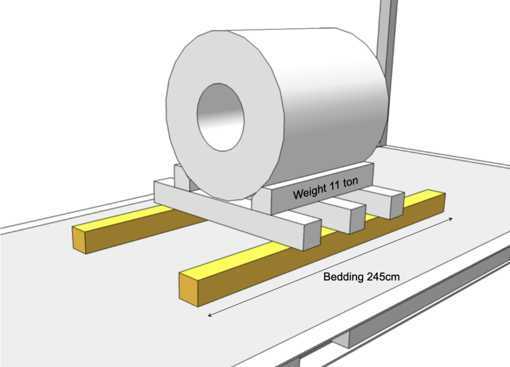
An 11-tonne Coil therefore requires an effective Bedding length of at least approximately 2.45 m.
In an actual calculation, the result must not be rounded down. It should be rounded up to remain on the safe side. If the weight of the Cradle or other supporting structure is significant, it must also be added to the Coil weight.
6. Why the Two Bedding Beams Should Be at Least 1 m Apart
Two Bedding Beams should be installed as a pair in the longitudinal direction of the container, with a spacing of at least 1 m between them. Each Beam should be positioned at least 50 cm from the container centerline and as close to the sidewalls as practicable.
This arrangement has the following structural benefits:
- It distributes the Coil weight over a wider transverse area.
- It improves the transverse stability of the Cradle.
- It moves the points of load application closer to the Bottom Side Rails and away from the centers of the Bottom Crossmembers.
- It reduces the bending moment at the center of each Crossmember.
- It allows the load to be transferred efficiently into the left and right Bottom Side Rails.
The 1 m spacing is therefore not intended to establish a permissible load per square metre. Nor is it derived directly from the wheel spacing used in the ISO Floor Test.
The Floor Test and the Bedding spacing are related in that both seek to prevent local overloading of the container floor. The 1 m Bedding spacing, however, is a separate loading criterion intended to distribute the Coil load toward the structural members on both sides of the container.
7. Calculating the Free End and Timber Section
The Free End is the length by which a Bedding Beam extends outward beyond each end of the Cradle or other supporting structure.
If the Cradle is centered on the Bedding Beam, the Free End is calculated as follows:
If the required Bedding length for an 11-tonne Coil is 2.45 m and the Cradle length is 1.0 m:
If the Cradle is not centered on the Bedding, the Free End must be calculated separately at the front and rear. The longer value should be used to determine the required Timber section.
General formula using both Timber width and height
The TT Club/CINS guidance calculates the maximum permissible Free End as follows:
- E : maximum permissible Free End length (cm)
- b : horizontal Timber width (cm)
- h : vertical Timber height or thickness (cm)
The formula can be rearranged to determine the required Timber height:
Simplified calculation for square Timber
If the Timber has a square (s x s) section, the general formula simplifies to:
The required side dimension of a square Timber section is therefore:
Applying this to the 11-tonne Coil example:
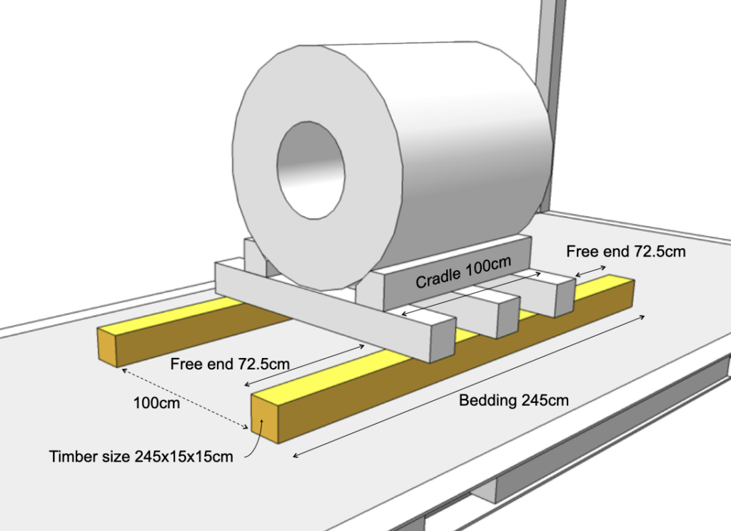
Rounding this result up to the next available size, Timber with an actual section of at least 15 × 15 cm is required.
The following Bedding arrangement can therefore be considered for this example:
- Length: at least 2.45 m
- Section: at least 15 × 15 cm based on the actual finished dimensions
- Quantity: two longitudinal Timber Beams
- Spacing between Beams: at least 1 m
- Position: as far from the container centerline as practicable and close to the left and right sidewalls
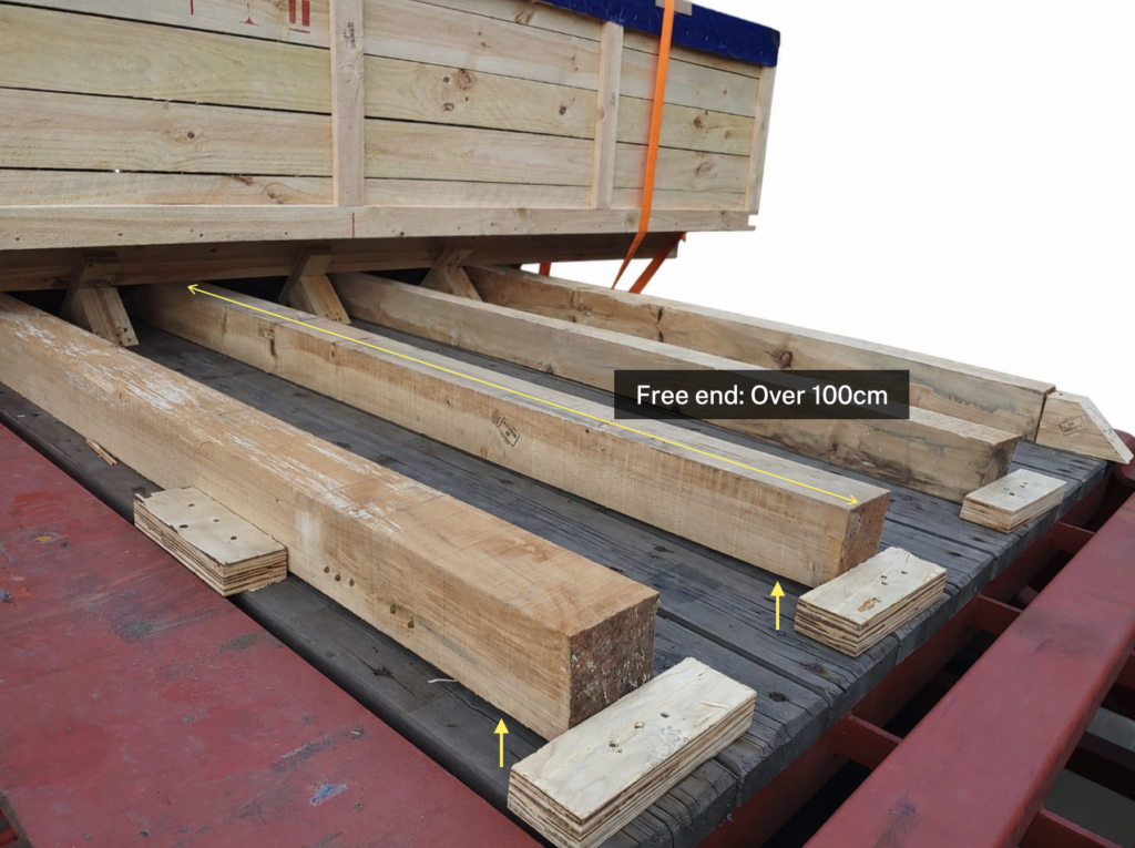
The guidance explains that when the Free End exceeds 100 cm, the ends of the Timber may bend upward or lose contact with the floor, preventing the load from being transferred along the full length. If the Free End exceeds 100 cm, the Timber should not simply be made progressively longer. The following alternatives should instead be considered:
- Increase the contact length of the Cradle itself.
- Use Steel Bedding or an engineered Load-Distribution Frame.
- Use a Flat Rack or a purpose-built Coil Container.
This formula is a practical guide for selecting a Timber size; it does not replace a complete structural design of the timber support. In actual use, the timber species, strength grade, knots, cracks, warping, moisture content, compressive strength, and actual finished dimensions must also be checked.
The Timber must be sufficiently dry and treated in accordance with ISPM 15, the International Standards for Phytosanitary Measures.
8. How Can the 11-Tonne Criterion Be Understood?
Carrier Coil-loading guidelines often limit the weight of a single Coil to 11 tonnes or less and require consideration of a Flat Rack with a stronger floor when the weight exceeds 11 tonnes.
Although the guidelines do not directly explain how the 11-tonne value was derived, applying the line-load criterion for a 20′ container together with the Free End criterion for 15 × 15 cm Timber reveals the following numerical relationship:
- Cradle length: 1.0m
- Maximum Free End for 15 × 15 cm Timber: 0.725 m at each end
- Effective Bedding length: (1.0+0.725+0.725=2.45m)
- Allowable line load for a 20′ container: 4.5 t/m
In other words, a representative arrangement using a 1 m Cradle and 15 × 15 cm Timber produces a calculated value of approximately 11 tonnes.
It can therefore be inferred that the 11-tonne criterion in the guidance is a conservative operational limit established by rounding this result downward and allowing for variations in the Timber and container condition. This is a technical inference based on the relationship between the figures, not an officially stated basis for how the guideline was established.
9. The Roles of Blocking and Bracing
If Bedding is the structure that distributes the vertical load, Blocking and Bracing are the structures that prevent the Coil from sliding, rolling, or shifting during transport.
Although the two terms are sometimes used interchangeably, their roles can be distinguished as follows:
- Blocking: Members installed close to the Coil or Cradle to restrain movement directly
- Bracing: Members that transfer and distribute the forces acting on the Blocking into suitable structural parts of the container
Blocking and Bracing do not increase the vertical load-bearing capacity of the Coil support. The Bedding calculation must first be satisfied, after which the Blocking and Bracing must be designed to control the longitudinal and transverse inertial forces generated during transport.
Bracing must extend toward the sidewalls
Bracing supporting the Bedding or Cradle should extend toward the container sidewalls. It must not be installed so that the end of one short Timber member applies a high concentrated load to a single point on the sidewall.
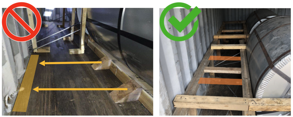
The sidewalls and end walls of a GP Container are not designed to resist high localized pressure. Horizontal Spreader Timbers or similar members should therefore be used to engage as many corrugations as practicable and distribute the force over a wide area.
The design strengths of the walls are as follows:
| Wall | Design strength |
|---|---|
| Entire sidewall | 60% of the maximum payload |
| Entire front or rear end wall | 40% of the maximum payload |
These figures apply when the load is distributed uniformly across the entire wall. They are not Point Load ratings that can be applied directly when the end of a small Blocking member contacts the wall.
Where practicable, Blocking at the closed end should use the recessed inner faces of the Corner Posts together with a suitable bulkhead so that the force is transferred into the End Frame.
Do not use the doors as a Blocking structure
Neither the Coil nor any Blocking structure should come into direct contact with the container doors.
If the Coil shifts during transport and presses against the doors, the doors may spring open when the locking gear is released, or the cargo may be forced out of the container and strike the operator.
A separate safety bulkhead and Blocking arrangement should therefore be installed on the door side, with sufficient clearance to prevent contact between the structure and the doors.
10. The Role and Limitations of Lashing
Lashing is a supplementary securing method applied after Blocking and Bracing have been completed.
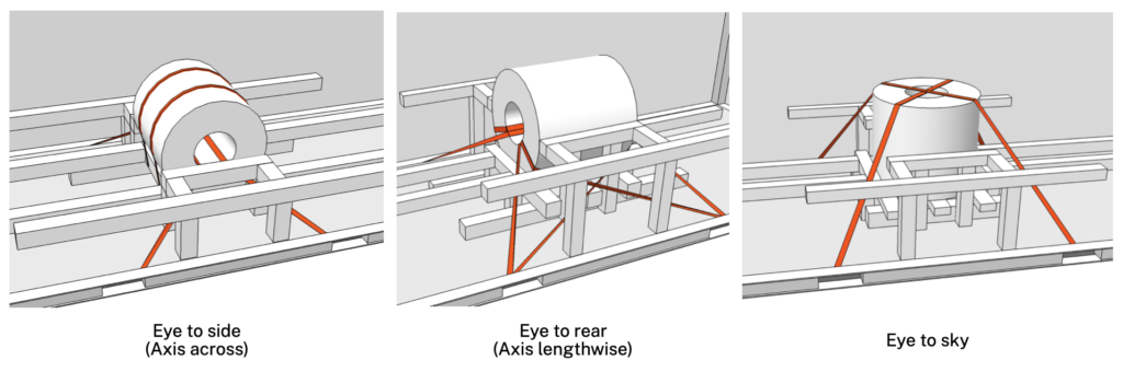
Its principal functions are to:
- Prevent the Coil from overturning.
- Prevent the Coil from becoming dislodged from the Cradle or Bedding.
- Limit the initial movement that can occur within small clearances in the Blocking.
- Provide additional protection against repeated dynamic loads during transport.
Lashing restrains horizontal movement and overturning. The vertical weight of the Coil must still be carried by the Cradle, Bedding, floor, and Crossmembers. Stronger Lashing cannot compensate for insufficient Bedding length.
Use of Anchor Points
Lashings must be connected to designated structural fittings, such as approved Anchor Points along the lower sides of the container.
The lashing capacity of Anchor Points in a typical Dry Van is approximately 1,000–2,000 kg. The specifications of the Anchor Points in the actual container and the carrier’s requirements must nevertheless be confirmed for the design.
The total securing capacity cannot be calculated simply by multiplying the number of Anchor Points by their rated capacity. Lashing angles, directions, friction, variations in pretension, and simultaneous load sharing must all be considered.
As a general rule, only one Lashing should be connected to each Anchor Point.
Precautions When Using Web Lashings
- Do not tie knots in the ends of Web Lashings, as doing so can reduce their strength by as much as approximately 50%.
- Use Edge Protectors wherever the Webbing contacts a sharp Coil edge.
- Excessive pretension can damage the Coil packaging, Bands, or Coil edges.
- A loose Lashing may engage only after an impact occurs, creating a high shock load on the Anchor Point.
- Before use, inspect the Webbing for cuts, abrasion, heat damage, and contamination.
Half-loop Lashing
A Half-Loop Lashing starts at an Anchor Point on one side, passes around the Coil, and returns to an Anchor Point on the same side.
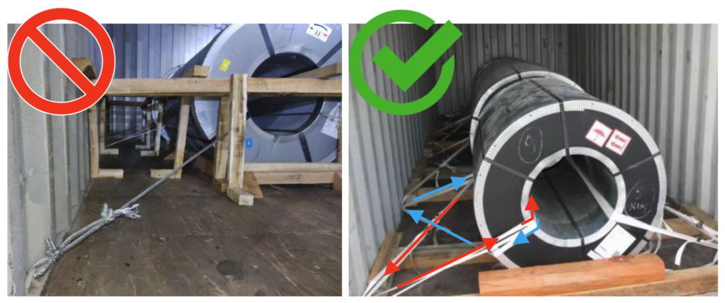
If installed on only one side, it cannot adequately restrain movement in the opposite direction. Half-Loop Lashings must therefore be installed as an opposing pair on both the left and right sides. Where necessary, corresponding arrangements should also be installed in the fore-and-aft direction so that the Coil is controlled in all principal directions.
A Half-Loop Lashing is not a substitute for Blocking. The two methods must be used together: Blocking directly restrains sliding, while the Half-Loop Lashing provides supplementary control against overturning and residual movement.
11. Center of Gravity and Coil Positioning
The position of a heavy Coil affects both the floor loading and the securing forces.
- A single Coil should be positioned close to the longitudinal and transverse center of the container.
- Two Coils of equal weight should be positioned with one toward the front and the other toward the rear to distribute the longitudinal load evenly.
- When several Coils are loaded, they should be arranged so that the combined center of gravity does not deviate significantly from the center of the container.
- The vertical center of gravity should be kept as low as practicable and, in accordance with the guideline, at no more than half the height of the cargo space.
- The Bedding Beams for individual Coils must not overlap.
If the center of gravity is offset to one side or one end, unbalanced loads may arise during crane, Reach Stacker, Chassis, and ship-stowage operations.
12. Which Is More Suitable: a 20′ or 40′ Dry Container?
It is easy to assume that a 40′ Dry Van, with its longer internal space, is also safer for a heavy Coil. This may not be the case when the applicable line-load criteria are considered.
Using an 11-tonne Coil and a 1 m Cradle as an example:
| Assessment item | 20′ DV | 40′ DV |
|---|---|---|
| Allowable line load | 4.5 t/m | 3.0 t/m |
| Required Bedding length | 2.45m | 3.67m |
| Free End with a 1 m Cradle | Approximately 72.5 cm | Approximately 133.5 cm |
| Applicability of the Timber guideline | 15 × 15 cm section can be considered | Free End exceeds 100 cm |
For a 40′ Dry Van, the required Bedding length for an 11-tonne Coil is approximately 3.67 m:
With a 1 m Cradle, the Free End is approximately 133.5 cm, exceeding the 100 cm limit in the Coil-loading guideline.
Additional measures are therefore required, such as:
- Increasing the contact length of the Cradle
- Using Steel Bedding or an engineered Load-Distribution Frame
- Confirming the actual floor specifications of the 40′ container
- Obtaining separate technical approval from the carrier
- Changing the equipment to a Flat Rack
For a single concentrated heavy Coil, a 20′ Dry Van with a higher allowable line-load criterion may therefore be more suitable than a longer 40′ Dry Van.
13. Practical Container-Selection Criteria by Coil Weight
The following figures provide conservative preliminary screening criteria for a single Coil:
| Weight of one Coil | Recommended assessment approach |
|---|---|
| 11 tonnes or less | Assess the feasibility of loading into a 20′ Dry Van. The Bedding length, Timber section, container condition, and securing plan must all be satisfactory. |
| More than 11 tonnes and up to 15 tonnes | Consider a Flat Rack as the primary alternative. A Dry Van should be considered only as an exception where Steel Bedding or an engineered Frame is used and special carrier approval has been obtained. |
| More than 15 tonnes | Treat the Coil as outside the normal application range of a general-purpose Dry Van and consider a Flat Rack, purpose-built Coil Container, or Breakbulk shipment. |
The 11-tonne criterion is not an absolute ISO limit applicable to every carrier and every Dry Container.
In practice, the following is a prudent interpretation:
Under the conservative criteria applied to a carrier’s mixed fleet, 11 tonnes per Coil should be regarded as the general upper limit for a Dry Container. Above this weight, a Flat Rack should be considered the primary equipment option.
A Coil weighing 11 tonnes or less is not automatically approved for Dry Container loading. In particular, the lower line-load criterion for a 40′ Dry Van may prevent a practicable Timber Bedding arrangement even for a Coil weighing less than 11 tonnes.
A Flat Rack is not automatically safe for every heavy cargo either. Its actual maximum payload, Load Limit, concentrated-load capacity, camber, manufacturing year, repair condition, and Bottom Side Rail condition must be checked separately.
14. Practical Pre-Loading Checklist
When assessing the loading of a heavy Coil into a Dry Container, confirm the following:
- Have the individual and total Coil weights been measured accurately?
- Does the total weight, including the Cradle, Bedding, and securing materials, remain within the maximum payload?
- Have the carrier’s allowable line loads for 20′ and 40′ containers been confirmed?
- Has the required Bedding length been calculated and rounded up to remain on the safe side?
- Are the Timber Free End and section dimensions acceptable according to the calculation?
- Have the actual finished dimensions, moisture content, cracks, knots, and ISPM 15 treatment of the Timber been verified?
- Are the two Bedding Beams positioned at least 1 m apart?
- Are the container floor, Crossmembers, and Bottom Side Rails free from deformation and defective repairs?
- Do the Blocking and Bracing distribute the force over a wide area without creating localized wall pressure?
- Is the Blocking structure clear of the container doors?
- Are the number, angles, and directions of the Lashings and the LC of the Anchor Points suitable?
- Are the Half-Loop Lashings installed as an opposing pair on the left and right sides?
- Is the longitudinal and transverse center of gravity of the Coil appropriately positioned?
- Have the weight limits of the Forklift, Chassis, road, railway, terminal, and cargo-handling equipment been checked?
- Have the loading drawing and securing plan received the carrier’s prior approval?
15. Checking Forklift Loads During Loading
The feasibility of loading a heavy Coil into a Dry Container cannot be determined from the maximum payload alone.
| Item | Criterion |
|---|---|
| Front Axle Load, including the Forklift and cargo | Maximum 5,460kg |
| Contact area per tire | Minimum 142㎠ |
| Tire width | Minimum 18cm |
| Wheel spacing on the same axle | Minimum 76cm |
These are separate Floor Load criteria for Forklift operations. The minimum 1 m spacing between Bedding Beams was not derived directly from the 76 cm Forklift wheel spacing.
It is therefore necessary to check not only the final Bedding arrangement after loading, but also whether the floor and Crossmembers could be damaged while the Coil is being moved into the container.
16. Conclusion
Even if the Line Load of the Coil in its final loaded position is within the allowable limit, a Forklift carrying the Coil into the container may apply a greater local load to the floor during the loading operation.
The most important requirement is to distribute the Coil weight over sufficient length and width, creating the following load-transfer path:
Coil → Cradle → Bedding Beams → Multiple Bottom Crossmembers → Bottom Side Rails → Corner Structurettom Side Rail → Corner Structure
Blocking and Bracing must then restrain the Coil against movement and rolling, while Lashing provides additional control against overturning and residual movement.
As a practical approach, the feasibility of loading a single Coil into a 20′ Dry Van may be assessed when it weighs 11 tonnes or less, provided that the required Bedding length, Timber section, equipment condition, and securing plan are all satisfactory.
When the Coil exceeds 11 tonnes, a Flat Rack should be considered the primary alternative. A Coil exceeding 15 tonnes should generally be treated as outside the normal application range of a general-purpose Dry Container.
These conservative criteria do not imply that every older container is necessarily weak. Their purpose is to manage structural uncertainties that are difficult to verify across a mixed fleet whose equipment varies in manufacturing year, repair history, floor construction, and residual strength.