

The fact that the 40′ Flat Rack states a maximum payload of 47 tonnes does not mean that any 47-tonne cargo, regardless of its configuration, can be loaded without further evaluation. The actual permissible cargo weight depends not only on the total cargo weight, but also on where the load is applied, the spacing between support points, the stiffness of the cargo and its supporting structure, the local bearing area, and the condition of the Bottom Side Rails.

Based on the Point Loading Chart and Uniform Loading Chart for a 40′ Flat Rack, this article examines the differences between the two loading methods, the structural significance of Bottom Side Rail camber, methods of distributing loads through Saddles, Skids, and Dunnage, and the criteria for selecting equipment for exceptionally heavy cargo.
1. Maximum Payload vs. Actual Permissible Cargo Weight
The maximum payload of a Flat Rack is an upper limit that applies when the container is in sound structural condition, the cargo is properly positioned and supported, and the load is transferred through a method permitted by the design.
The actual permissible cargo weight may therefore be lower than the stated payload if any of the following conditions apply:
- The effective support length is too short.
- The cargo weight is concentrated near the center of the Flat Rack.
- The bearing area of a Saddle or timber support is too small.
- The load is transferred only to the timber Floor or a limited number of Crossmembers.
- The center of gravity is offset from the center of the container.
- The camber of the Bottom Side Rails has decreased or permanent sagging is present.
- Corrosion, cracking, deformation, or a repair history involving major structural members is identified.
2. Point Load and Uniform Load
On a Flat Rack Loading Chart, a Point Load does not mean that the cargo weight acts on a single point on the Floor. Because the chart shows the Flat Rack in side elevation, an actual transverse line of support appears as a single point.
Point Load
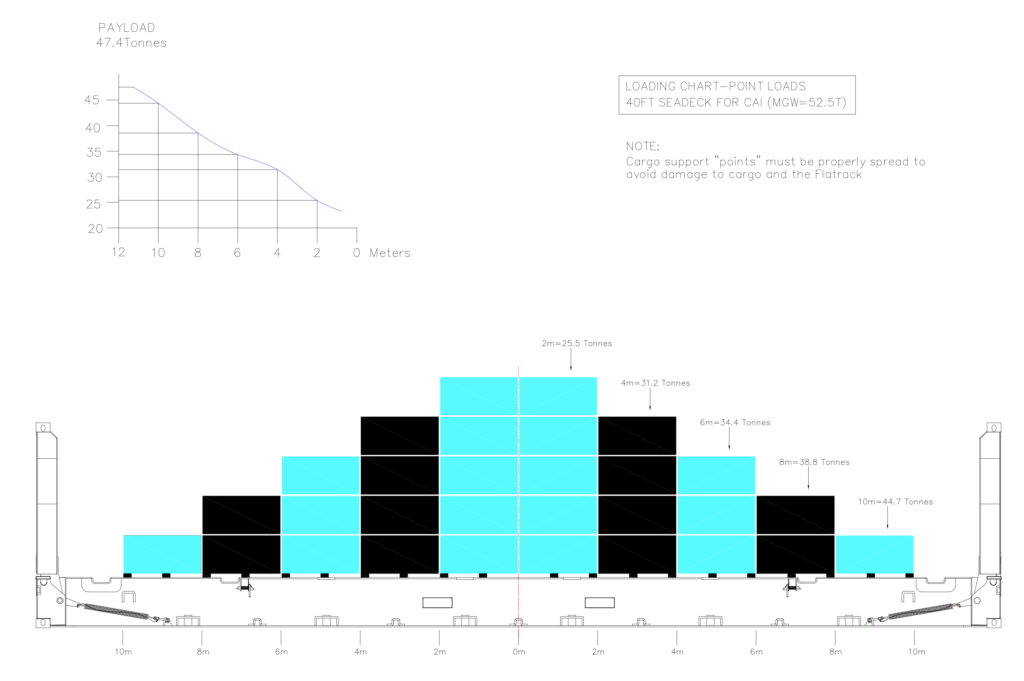
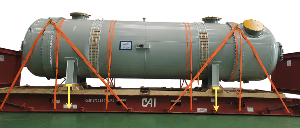
Under a Point Load arrangement, sufficiently stiff cargo is supported at two principal bearing locations along its length. Each Saddle or transverse support must extend across the Flat Rack and transfer the load to both Bottom Side Rails. The value shown in metres (m) on the chart generally represents the longitudinal spacing between the two principal support points, not the overall length of the cargo.
(Source: CAI International, Reproduced with permission from CAI Korea. This material is provided for guidance in support of safe container transport.)
Uniform Load
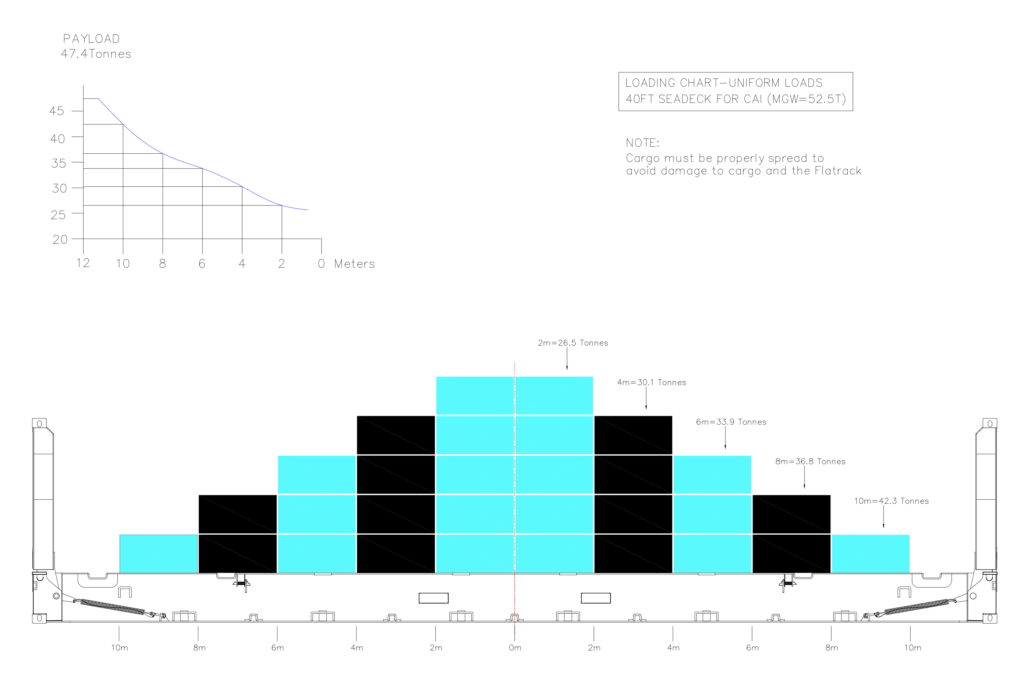
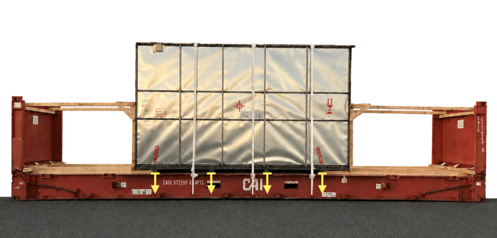
Under a Uniform Load arrangement, the cargo weight is transferred approximately evenly over a defined longitudinal length. This includes cases in which a continuous Skid or bottom base remains in actual contact throughout the entire span, or the cargo is otherwise supported continuously. The value shown in metres (m) on the chart represents the effective length over which the load is uniformly distributed.
(Source: CAI International, Reproduced with permission from CAI Korea. This material is provided for guidance in support of safe container transport.)
A comparison of the permissible weights shown on the same 40′ Flat Rack Loading Chart is provided below.
| Effective support spacing/length | Point Load | Uniform Load |
|---|---|---|
| 2 m | 25.5 t | 26.5 t |
| 4 m | 31.2 t | 30.1 t |
| 6 m | 34.4 t | 33.9 t |
| 8 m | 38.8 t | 36.8 t |
| 10 m | 44.7 t | 42.3 t |
* These figures are examples applicable only to the relevant CAI equipment series. For Flat Racks from other manufacturers, production series, or structural designs, refer to the Loading Chart applicable to the specific equipment.
3. Why Point Loading Can Permit More Weight Than Uniform Loading
It is generally assumed that spreading a load over a wider area is beneficial to a structure. This is correct from the perspective of local bearing pressure. When the overall longitudinal bending of a Flat Rack is considered, however, the result can be different.
The Bottom Side Rails on both sides of a 40′ Flat Rack are long primary structural members connecting the Corner Fittings. If they are simplified as beams supported at both ends, the bending moment at the center varies according to where the load acts, even when the total weight and the supported span are the same.
Under the Point Load condition, the two support points are positioned toward the outer ends of the supported span. As the spacing between them increases, each load moves farther from the center and closer to the Bottom Corner Fittings. This can reduce the maximum bending moment and downward deflection at the center of the Bottom Side Rails.
Under the Uniform Load condition, by contrast, the load acts throughout the same span, including the central region where the camber is greatest. For the same total cargo weight, the bending moment at the center may therefore be greater.
The important point is that Point Loading is not advantageous because the load is concentrated. Its advantage arises from positioning the two principal load points farther apart, allowing the load to be transferred closer to the Corner Fittings and reducing the overall bending of the Flat Rack.
Over a 2 m span, the permissible Uniform Load is instead one tonne higher. This suggests that when the two Point Loads are located close together near the center, the benefit of reducing overall bending becomes small, while the effects of local stresses in the Side Rail flanges and webs, Crossmembers, and bearing areas may become relatively more significant.
4. Camber
Heavy-duty 40′ Flat Racks are designed with camber, meaning that the center of each Bottom Side Rail curves upward when the unit is empty. The relevant 40′ Flat Rack specification indicates a camber of approximately 50 mm.
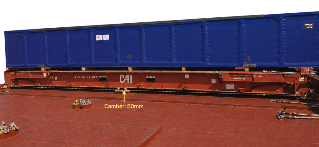
Camber is an initial structural profile intended to accommodate the downward deformation that occurs when cargo is loaded, allowing the Bottom Side Rails to remain within their permissible deformation range. Camber itself, however, does not increase the ultimate strength of the steel or automatically provide additional payload capacity.
When Point Load support locations are moved outward, reduced bending at the center can limit the loss of camber and additional downward deflection. Conversely, a load concentrated near the center or a Uniform Load acting over a broad area may cause a greater reduction in camber.
Camber is therefore important structural context when interpreting a Loading Chart. However, the direct reason that Point Loading can permit more weight is the reduction in the overall bending moment resulting from the locations of the applied loads.
5. The Disadvantage of Point Loading: Higher Local Loads
Point Loading may reduce the overall bending of the Bottom Side Rails, but it increases the reaction at each bearing location.
For example, if a 40-tonne cargo with its center of gravity at the midpoint is supported by two Saddles, the static reaction at each Saddle is approximately 20 tonnes. Even if each Saddle transfers the load equally to the left and right Bottom Side Rails, approximately 10 tonnes will act at each Side Rail contact area.
In practice, the load may not be divided equally because of an offset center of gravity, differences in the stiffness of the cargo and Skid, variations in Saddle height, camber, and manufacturing tolerances. Dynamic effects arising during transport and cargo handling must also be considered.
Excessive local loading can cause the following types of damage:
- Crushing or bending failure of a Saddle or timber support
- Local deformation of the cargo shell or bottom Frame
- Indentation, cracking, or failure of the timber Floor
- Deformation of Crossmembers
- Local bending of the upper flange of a Bottom Side Rail
- Local crushing or buckling of a Side Rail web
- Cracking of welds or propagation of existing damage
Compliance with the permissible weight shown on a Point Loading Chart does not, by itself, establish that a proposed loading arrangement is suitable. A Loading Chart addresses specified load conditions for the Flat Rack as a whole; it does not automatically verify the strength of the actual Saddles, Skids, and Dunnage or the local bearing pressure at each contact area.
The Floor Strength stated in an equipment specification is also a test value based on a specified test vehicle and defined wheel or axle load conditions. It must not be interpreted directly as the permissible reaction for an individual Saddle.
6. The Most Effective Approach to Loading Heavy Cargo
The ideal approach to loading heavy cargo is not simply to choose either Point Loading or Uniform Loading.
At the overall longitudinal structural level, the principal support points should be positioned appropriately. At each bearing location, the load should then be distributed over a sufficient area.
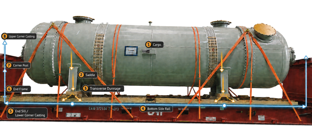
The basic load path is as follows:
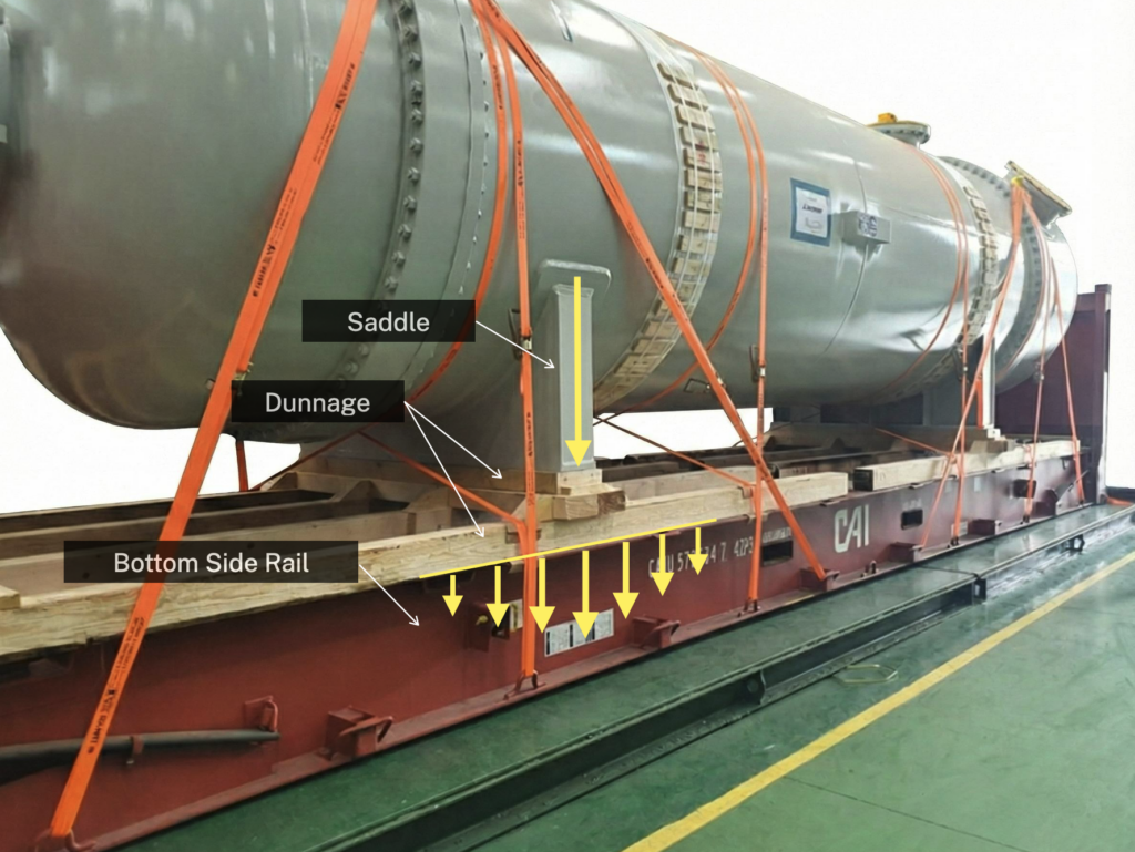
① Cargo → ② Saddle, Skid or load-distribution Frame → ③ Transverse Dunnage or load-spreading Beam → ④ Left and right Bottom Side Rails → ⑤ End Sills and Lower Corner Castings
When the Flat Rack is lifted by its Upper Corner Castings, the load is transferred through ⑥ the End Frames and ⑦ Corner Posts to ⑧ the Upper Corner Castings.
| Component | Primary function |
|---|---|
| Saddle | Matches the curvature of cylindrical cargo, provides stable support, and restrains rolling and movement |
| Skid or load-distribution Frame | Connects multiple Saddles into a stiff structure and stabilizes load transfer |
| Transverse Dunnage or load-spreading Beam | Transfers the cargo weight to the left and right Bottom Side Rails |
| Wide bearing plate or timber | Reduces bearing pressure and local stress in the Side Rails at each contact area |
| Shimming | Compensates for camber, manufacturing tolerances, and differences in support height so that the intended bearing points share the load |
The key is not to place narrow Saddles directly on the timber Floor, but to install a load-distribution structure with sufficient strength and bearing area so that the load at each principal support location is transferred reliably to both Bottom Side Rails.
7. How Many Saddles Are Appropriate?
For relatively light cargo, two Saddles—one toward each end—are often sufficient to provide stability and support. For exceptionally heavy cargo, the reactions concentrated at two Saddles may become substantial, and additional Saddles or another load-distribution structure may be required.
However, a universal rule such as “at least three Saddles for cargo over 40 tonnes” is difficult to justify. In the Point Loading Chart example, up to 44.7 tonnes is permitted when the spacing between support points is 10 m. This means that cargo exceeding 40 tonnes can still be supported at two principal bearing zones, provided that the cargo and supporting structure have sufficient stiffness and each local contact area has been verified.
Conversely, increasing the number of Saddles does not automatically distribute the load equally. A 40′ Flat Rack has camber at its center, and small differences exist in the height and stiffness of multiple Saddles. As a result, a central Saddle may make contact first and carry more load than expected, while the outer Saddles may not develop their intended share of the load.
Multi-point support using three or more Saddles makes the distribution of structural reactions more complex. The load at each Saddle must not be calculated simply by dividing the total weight by the number of Saddles. Actual load sharing should be managed through the following measures:
- Use of a sufficiently stiff continuous Skid or load-distribution Frame
- Saddle heights designed to account for the Flat Rack’s camber
- Precise Shimming and verification of full contact at all intended bearing surfaces
- Calculation of the reaction at each support point based on the cargo’s actual center of gravity
- Review by a structural engineer or professional Surveyor where necessary
The decisive factor is therefore not the number of Saddles, but a load-transfer structure that allows the reaction at each support point to be predicted and controlled.
8. Older Equipment That Has Lost Its Camber
Some 40′ Flat Racks that have been in service for many years show little remaining camber even when empty, or have Bottom Side Rails whose centers sit close to the ground.
If a model was originally designed with camber but its center touches the ground or its camber has decreased significantly, the following conditions should be suspected:
- Permanent sagging caused by repeated transport of heavy cargo
- Previous overloading or improper Point Loading
- Plastic deformation of the Side Rails
- Fatigue cracking or weld damage
- Loss of effective structural section due to corrosion
- Improper repairs to major structural members
The permissible weights in a Loading Chart, which assume equipment in sound structural condition, cannot readily be applied to such a unit. In particular, it should not be assigned to cargo weighing 40 tonnes or more unless it has undergone a detailed inspection by the equipment owner and its structural suitability has been confirmed.
9. Selecting Equipment for Exceptionally Heavy Cargo
For cargo weighing 40 tonnes or more, giving priority to a recently manufactured, lightly used, heavy-duty 40′ Flat Rack is a reasonable practical policy.
Newer equipment is generally more likely to have the following characteristics:
- Less accumulated fatigue from repeated loading
- A greater likelihood that the designed camber has been maintained
- A lower likelihood of corrosion and loss of structural section
- Less likelihood of major repair history involving the Side Rails, End Sills, or Corner Fittings
- Less likelihood of previous overloading or impact damage
A recent manufacturing date alone, however, does not guarantee safety. New equipment can also be damaged by collision, dropping, overloading, or improper loading, while older equipment may remain in sound structural condition if it has been properly inspected and maintained.
The best selection criterion is therefore not simply the year of manufacture, but equipment that satisfies all of the following conditions:
- The Loading Chart applicable to the proposed cargo has been identified.
- The camber and major structural members are in sound condition.
- The unit is recently manufactured, lightly used, and has no history of major structural repairs.
10. Conclusion
The objective of loading heavy cargo on a 40′ Flat Rack is neither to minimize the number of Saddles nor simply to spread the load as widely as possible. The essential requirement is to design the support arrangement so that the cargo load follows the intended path into the left and right Bottom Side Rails and the Corner Casting structure.
In practice, this can be summarized in three principles:
- At the overall longitudinal structural level, reduce bending at the center by positioning the principal support points an appropriate distance apart.
- At each bearing location, combine Saddles, Skids, and Dunnage to distribute local loads over a sufficient area.
- For exceptionally heavy cargo, select structurally sound equipment for which the applicable Loading Chart and camber have been confirmed.
As shown in the photograph below, the most effective design is a hybrid load-distribution arrangement that takes advantage of Point Loading at the overall structural level while creating Distributed Loading at each local bearing area.